

GT STRUDL® is one of the most widely used Structural Design & Analysis software programs for Architectural – Engineering – Construction (AEC), CAE/CAD, utilities, offshore, industrial, nuclear and civil works. GT STRUDL® is a fully integrated general-purpose structural information processing system capable of supplying an engineer with accurate and complete technical data for design decision making.
GT STRUDL® completely integrates graphical modeling and result display, frame and finite static, dynamic, and nonlinear analysis, finite element analysis, structural frame design, graphical result display, and structural database management into a powerful menu driven information processing system. In over 35 years of use, GT STRUDL® is one of the most widely accepted computer-aided engineering and design tools for the structural analyst and structural design engineer. GT STRUDL® support and quality assurance standards offered by the INTERGRAPH are among the most rigorous in the industry. GT STRUDL® software certification procedures are in full conformance with the applicable provisions of the U.S. Nuclear Regulatory Commission and the U.S. Department of Energy Quality Assurance and Quality Control regulations.
Finally, CAD Modeler, an add-on to AutoCAD®, provides a powerful graphical user interface to GT STRUDL® and which creates a highly user-friendly and productive modelling environment.
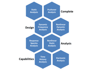
Multiple Analysis Modalities
GT STRUDL offers comprehensive frame and finite element analysis tools for the linear and nonlinear static and dynamic analysis of general 3D structural problems. You can take advantage of five member types and an extensive library of finite elements based on a broad range of:
- Plane strain
- Plane stress
- Pure plate bending
- Shell
- Solid element formulations
Integration of Various Members and Analysis Modalities
Engineers can create structure models consisting of appropriate combinations of the various member and finite element types that best meet the analysis requirements of the engineer-analyst.
The breadth and depth of functionality enables engineers to analyze the broadest range of projects, from the simplest to the most complex structural models. Regardless of the project size, GT STRUDL produces accurate and reliable results, often in a fraction of the time of other programs.
Modeling and Analysis
Users benefit from a variety of modeling and analysis capabilities, including:
- Linear and nonlinear static and dynamic analysis
- High performance static and dynamic analysis equation solvers
- Lanczos Eigen value solver, including the ability to specify computation convergence tolerances
- Sturm sequence, error estimate, and two orthogonal checks
- User-defined translation and rotation mass
- Active/Inactive Mode Selection
- Response Spectrum Analysis
- RMS, PRMS, CQC, Absolute, Algebraic, Ten-Percent, Double Sum, and Grouping mode combination methods
- Gupta and Lindley-Yow mode combination methodologies
- Missing mass load generation
- Broad range of user-specified damping properties, including Modal Damping, Composite Modal Damping, Rayleigh Damping, Damping Matrix, and Viscous Damper Elements
- Composite modal damping ratio calculations
- Time history dynamic analysis
- Maximum response harmonic analysis for individual frequencies or for a range of frequencies (i.e. frequency sweep analysis)
- Steady state dynamic analysis
- User-controlled and variable integration time steps
- Nonlinear Pushover Analysis
- Nonlinear spring elements, support and member end springs, tension, and compression-only members, large sag catenary and parabolic cables
- Nonlinear fiber element plastic hinge and plastic zone member models
- Base Isolation friction-bearing damper element
- Structural analysis database management
- Automatic mesh generation in cartesian, cylindrical, and spherical reference frames
- Scalable problem size modeling
- Broad range of static and dynamic loading types
- Integer and alphanumeric naming
- Model error detection
Comprehensive Steel Design
Structural engineers can perform steel member design and code-checking to meet a large variety of global steel design codes dating back to the 1960s. These details are extensively documented, enabling the engineer to review the details of the code-checking procedures.
With GT STRUDL, engineers can manage the steel member design and code-checking process through a large number of control options, including:
- Control parameters
- Specification of absolute and relative geometric constraints
- Member size smoothing options
- Automatic analysis and design iterations
International Members Design Codes
In addition to approximately 80 pre-defined tables of steel shapes, engineers may also define and store custom shapes in user-defined tables.
GT STRUDL steel design offers a variety of international steel design codes, including American, European, Canadian, British, and Indian codes for onshore steel frame structures, and American, ISO, and Norwegian codes for offshore jacket design.
Design Capabilities:
- Structural steel
- Transmission towers
- Offshore jackets
- I, T, channel, single/double angles, pipes, tubes, bars, and others
Special Features
Users benefit from a variety of steel design capabilities, including:
- Steel Design Wizard
- Automatic analysis, design, and member smoothing
- Absolute and relational geometric constraints
- Automatic member self-weight calculations
- Effective length factor calculations
- Member deflection check and design
- Material quantities report
- Fillet weld design
- Default and user-defined tables of steel shapes

International Design Codes
GT STRUDL steel design offers a variety of international steel design codes, including American, European, Canadian, British, and Indian codes for onshore steel frame structures, and American, ISO, and Norwegian codes for offshore jacket design.
American Steel Design Codes
- AISC 14th, 13th, and 9th Editions
- AISC ASD and LRFD
- AISI Cold-formed Steel for UNISTRUT shapes
- ANSI/AISC N690 2012, 2006, and 1994 Editions
- ASME BPVC Subsection NF 2007 and 2004 Editions
- ASME BPVC NF 2007, 2004, 1983/1985, and 1977/1979 Editions
- ASCE Manual No. 52 for Steel Transmission Towers, 1st & 2nd Editions
- ASCE/SEI 48-05 for Steel Pole Structures
- API (LRFD & WSD-20)
- API RP 2A-WSD 21st Edition
Other Steel Design Codes
- Eurocode 3 (EC3) 2005 Edition
- ISO 19902:2007(E)
- NPD (Norwegian OPD)
- British BS5950 2001 Edition
- BS5950 (British LSD)
- BS449 (British ASD)
- CAN97 (Canadian)
- Indian Standard IS800 1984 Edition
Base Plate Wizard (BPW)
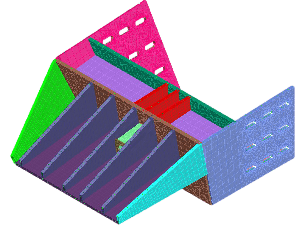
The Base Plate Wizard (BPW) is a graphics-based tool that helps you create models of base plates anchored to bearing surfaces with one or more attachments.
Base plate analysis models consist of:
- Plate
- Holes
- Notches
- Tabs
- Attachments
- Anchors
- Stiffeners
- Bearing surface data
- Boundary conditions representing shear lugs
- Edge welds
- Other relevant data
Engineers may specify:
- Plate Dimensions, notches, holes, and skewed edges
- Finite element mesh size
- Attachment location and rotation (up to 25 attachments per plate), including:
- AISC wide flanges, tubes, pipes, channels, tees, and angles
- User-defined shapes
- Attachments may be rotated in-plane
- Attachments may be modeled as an in-plane rigid solid or as a FE mesh extension
- Anchor location and properties
- Anchors (up to 1,000) may be modeled as linear or nonlinear springs, or as frame members, including tension-only members
- Bearing surface properties
- Bearing surface stiffness may be specified as Fc’, E, or F/L**3
- Gaps between the plate and bearing surface
- Stiffeners may be rectangular, trapezoidal, or triangular
- Modeling constraints not set by the bearing surface or anchors and loadings
- Constraints allow extra boundary conditions at specified node locations
- Cutouts enable modeling of tabs, holes, notches, and skewed plates
- Base plate models made be saved and recovered using .gtbp format
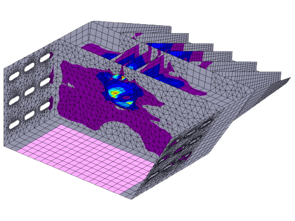
- Results (anchor forces, bearing surface pressure, plate stresses, and displacements) may be reviewed in the BPW

Import and Export of CIS/2 Files
GT STRUDL includes a bi-directional CIS/2 analysis model data interface to Intergraph SmartTM 3D. Engineers can take advantage of the extensive modeling features of Smart 3D and the powerful structural analysis and design capabilities of GT STRUDL. Other programs that use the CIS/2 model data format can also be interfaced to GT STRUDL.
Import of CIS/2 Files
GT STRUDL can read the following information from a CIS/2 analysis model data file:
- Joint/node location
- Joint/node support condition and release status
- Member (beam element) incidences
- Member profile and cardinal point
- Member beta angle
- Member end releases (pinned connections)
- Member eccentricities
- Load cases
- Applied joint loads
- Applied member loads (concentrated/distributed, local/global)
- Load combinations
- “Assembly maps” – Which analytical members compose a single physical member
Export CIS/2 Files
GT STRUDL can create a CIS/2 analysis model data file containing all the data listed for import, plus analysis results:
- Support reactions
- Joint/node displacements
- Member end forces
When exporting a CIS/2 analysis model, the user can select:
- Units (length and force)
- Whether to include applied loads or results
- Default steel grade
- Assumed member type (beam, column, or brace)
- Convert from a global Y-vertical axis to a Z-vertical axis
- Write analysis elements as physical elements
Reinforced Concrete Capabilities
With GT STRUDL, engineers can design concrete beams, columns, one-way slabs, shear walls, and two-way flat plate and flat slab structures per ACI 318. GT STRUDL also provides detailed quantity take-offs based on design results. A great deal of engineering time can be saved with this capability.
GT STRUDL also provides details of reinforcing bar lengths and arrangement details per user-controlled specifications, as well as beam-to-column joint details.
Concrete Component Design
- Beams
- Columns
- One-way slabs
- Shear walls
- Two-way flat slabs
Automatic Generation
- Building geometry
- Special members
- Floor slabs
- Wall panels
- Uniform floor loads
- Wind loads
Design Output
- Cross section dimensions
- Required area of steel
- Number and sizes of bars
- Placement of bars
- Spacing and cut-off points
- Stirrup/link sizes and spacing
- Critical design moments and shear for verification
- Number, size, and spacing of ties/spirals (for columns)
Special Features
- Detailed material take-off
- Beam-to-column joint details
- Seismic design and detailing
- User-specified design values
- Concrete girder definition
- P-Delta analysis

Offshore Capabilities
GTSTRUDL offers powerful capabilities for offshore analysis and design. A set of integrated features enable the engineer to perform the complex functions of sea environmental load computation, fatigue life analysis, jacket pile foundation analysis, and code checking of offshore structural strength and performance behavior.
GTSELOS
The computation of sea environmental loads is performed by the GTSELOS program. Various specialized analyses include:
- Static and dynamic wave and wind load analyses of fixed and floating jacket and semi-submersible structures
- Jacket launch analysis including the effects of both barge and jacket motion
- Jacket upending analysis
- Jacket floating stability analysis
The sea environment loads computed by GTSELOS are then easily imported by GTSTRUDL, where they are used to perform fatigue life analysis, jacket pile foundation analysis, and code-checking procedures.
Fatigue Life Analysis
Fatigue life analysis can be performed by one or more of three methods, including the Discrete Probabilistic Method, the Power Spectral Density Method, and the simple Deterministic Method. The fatigue life analysis includes load-dependent joint classification analysis according to:
- API and ISO standards
- SCF factor computations based on the Kuang, Smedley, and Efthymiou equations
- User-defined S-N fatigue data
- Cumulative damage computation based on the appropriate application of the Palmgren-Miner Law
Pile-Structure Interaction Analysis
Pile structure interaction analysis can be used for three-dimensional structures supported by nonlinear foundation pile members that are embedded in a nonlinear soil medium. The superstructure is described by a conventional GT STRUDL small deflection, linear elastic model. The pile-soil foundation can be modeled to include the:
- Soil nonlinear bending, axial, and torsional properties
- Inelastic load displacement properties of the pile
- Beam-column effect of the pile
- Ultimate axial capacity of the pile, taking into account skin friction along the pile
Code Checking
Standard tubular members can be checked according to the provisions of the latest API and ISO code provisions for:
- Tension
- Compression
- Bending
- Punching shear between brace and chord members
- Hydrostatic collapse
We gladly announce that ATLAS has been acquired by INTERGRAPH, and will be available in GTSTRUDL version 34 (2015) as CAD Modeler, under the same license with GTSTRUDL.
Our company, original developer of ATLAS (CAD Modeler), will continue developing it for INTERGRAPH.
CAD Modeler Concept
- Combines the ease of use of a well-known CAD system with the powerful and sophisticated Finite Element Analysis program GT.STRUDL so as to create new models faster
- This application is bringing the CAD environment closer to the modeling tool and FEA engine, since they all share the same database
- GTSTRUDL entities are created as custom objects, with their properties, making easier to overview and modify your existing models
Database Managment
- All data (structural data and analysis results) are stored in an SQL database, and can be retrieved by third party software. An API is also available for creating custom sections and retrieving data
- Graphic entities/objects interact directly with the SQL database (eg. if a joint is moved or deleted the database is automatically updated), with multilevel UNDO options
- All data are stored in only 2 files. The *.DWG file and the SQL *.db file that are linked together
- Supports all available Unit Systems in GT.STRUDL
CAD System
- Well known commands such as copy, move, mirror, array, stretch, extrude, etc are fully supported for custom structural entities
- Graphic entities/objects interact directly with the SQL database (eg. if a joint is moved or deleted the database is automatically updated), with multilevel UNDO options
- Standard AutoCAD objects such as Lines, Circles, Arcs, Polylines can be used as “construction” objects
- Unstructured and Structed powerfull mesh generator is available, handling arbitrary shapes with internal boundaries, holes and constraints
Mesh Generation
- Generating members along curves (arcs, linkes, circles, etc)
- Structured Mesh Generation defined by 2 Curves (members or elements) or by 4 Curves (members or elements)
- Unstructured Mesh Generation: Triangular meshing inside polylines, with internal holes and/or points. Control over size of elements, quality of elements
- Extruded Mesh Generation: Extrude Polyline along 3rd direction to generate quad elements
- Control over member, element and joint labeling
Available Objects
- Joint: Coordinates, Fixes, Theta angles, Kf spring values, Group
- Member: Connectivity, Beta Angle, Section properties, Material properties, Kf spring values, Eccentricities, Group
- Element: Connectivity, Type, Thickness, Group
- Loads: Joint, Member Load, Temperature Load, Distortions
- Load Combinations
GT STRUDL Quality Assurance Program Subscription 42
When GT STRUDL is used in/on projects related to the Nuclear Industry, the GT STRUDL QA and Reporting Annual Service is applicable and recommended.
The GT STRUDL Quality Assurance Program is based on written procedures, ASME NQA-1-2000, NRC (Nuclear Regulatory Commission) 10CFR21, and NRC 10CFR 50 Appendix B. The program includes the Verification Manual, associated test problems and solutions, three (3) day error notification, and customer audits. GT STRUDL Quality Assurance and Reporting Annual Service is an additional yearly service fee, which satisfies the requirements of US 10 CFR Part 50 Appendix B (QA Reporting).
For further information, please contact us.
GTSTRUDL Release Guides
Version
Date
- GTSTRUDL Version 44
- GTSTRUDL Version 43
- GTSTRUDL Version 42
- GTSTRUDL Version 41
- GTSTRUDL Version 40
- GTSTRUDL Version 2020 (39)
- GTSTRUDL Version 2019 (38)
- GTSTRUDL Version 2018 R1 (37.1)
- GTSTRUDL Version 2018 (37)
- GTSTRUDL Version 2017 (36)
- GTSTRUDL Version 2016 R2 (35.2)
- GTSTRUDL Version 2016 R1 (35.1)
- GTSTRUDL Version 2016 (35)
- GTSTRUDL Version 2016 (34)
- GTSTRUDL Version 33
- GTSTRUDL Version 32
- GTSTRUDL Version 31
- GTSTRUDL Version 30
- GTSTRUDL Version 29.1
- GTSTRUDL Version 29
- GTSTRUDL Version 28.1
- GTSTRUDL Version 28
- GTSTRUDL Version 27
- GTSTRUDL Version 26
2025 November
2024 November
2023 November
2022 November
2021 November
2021 November
2019 April
2018 July
2017 December
2017 April
2016 October
2016 March
2015 October
2015 February
2014 February
2012 June
2010 August
2009 April
2007 June
2006 December
2006 January
2005 January
2003 June
2002 February
CAD Modeler Getting Started Guide
Version
Date
2025 November
2024 November
2023 November
2022 November
2021 November
2020 May
2019 April
2018 July
2017 December
2017 April
2016 October
2016 March
2015 October
2015 February